High Performance Magloop

I’ve been experimenting with “magnetic” loop antennas for a few years now and running tests using WSPR (with hundreds of spots & statistical analysis) to drive out the losses from my antenna. I’ve had a lot of success using a largeish (7.5m circumference) loop antenna in the loft for 80m and 40m, where it easily outperforms -especially on low angle DX- any kind of wire antenna (loaded dipole, EFHW) that I can get into the available space.
In passing, a note on using thick conductors to maximise loop efficiency: Thick conductors can help reduce skin effect losses but “diminishing returns” apply after a reasonable thickness, especially in the presence of other losses such as connections, nearby lossy material etc. I have found 10mm soft copper tube to be a good compromise between losses, expense, and ease of handling / construction. The additional performance of thicker material, even going to 40mm diameter which would cost hundreds of £ for a 7.5m loop, is only about 1 to 1.5 dB.
I know from the “Ham Radio Web” that Vaccuum Variable Capacitors (VVC) are the gold standard for low loss capacitors in magloops, but I’ve achieved good results with air spaced variables and wanted to see how far I could push this without “giving in” and buying a VVC. Lessons learned with air spaced capacitors:
- Don’t rely on the wiper contact to connect to the moving plates. The wiper is a source of loss resistance - enough to make it melt & fail with just a bit of power! Instead, clamp a flexible wire to the spindle or solder one to the final moving plate.
- Use copper or aluminium for all connections - avoid steel and galvanized pieces (again, sources of loss resistance).
- It’s not always easy to notice capacitor arcing from a remote position, especially with SSB operation.
- However, with good connections, limited trials tell me that my air spaced capacitor is comparable with a VVC (which I finally gave in to buy and test) in terms of the impact on the gain of the antenna.
The remaining problem with air spaced capacitors is power handling; my air spaced capacitor will arc at about 20W on 80m and about 40W on 40m. If you can live with that, there’s no need for the VVC unless you’re tempted by the higher max:min capacitance ratio to squeeze in more bands. Also, VVCs are expensive and need more torque to turn than a typical air spaced capacitor, which means more mechanical design effort for the controller.
So I have been wondering - is there a way to use an air spaced capacitor in conjunction with fixed capacitors to improve the power handling?
The answer is “yes” - but it depends how far you want to push it and what other design compromises you’re willing to accept (notably, more limited tuning range).
Consider a magloop optimised for a single band, for which you only need a small swing of capacitance. What about providing the main capacitance by building a really high-Q air spaced capacitor out of fixed plates, with enough spacing for your max power, and using an air spaced variable to fine tune across the band? Potential advantages:
- Absolute design control over the main capacitor which can even potentially be mechanically integrated into the main loop as done with the Cirio Mazzoni Baby and Midi loops
- Lower voltage across the air spaced variable so better power handling
- Less current flowing through the air spaced variable, so lower losses caused by it
- More relaxed tuning (bandspread effect)
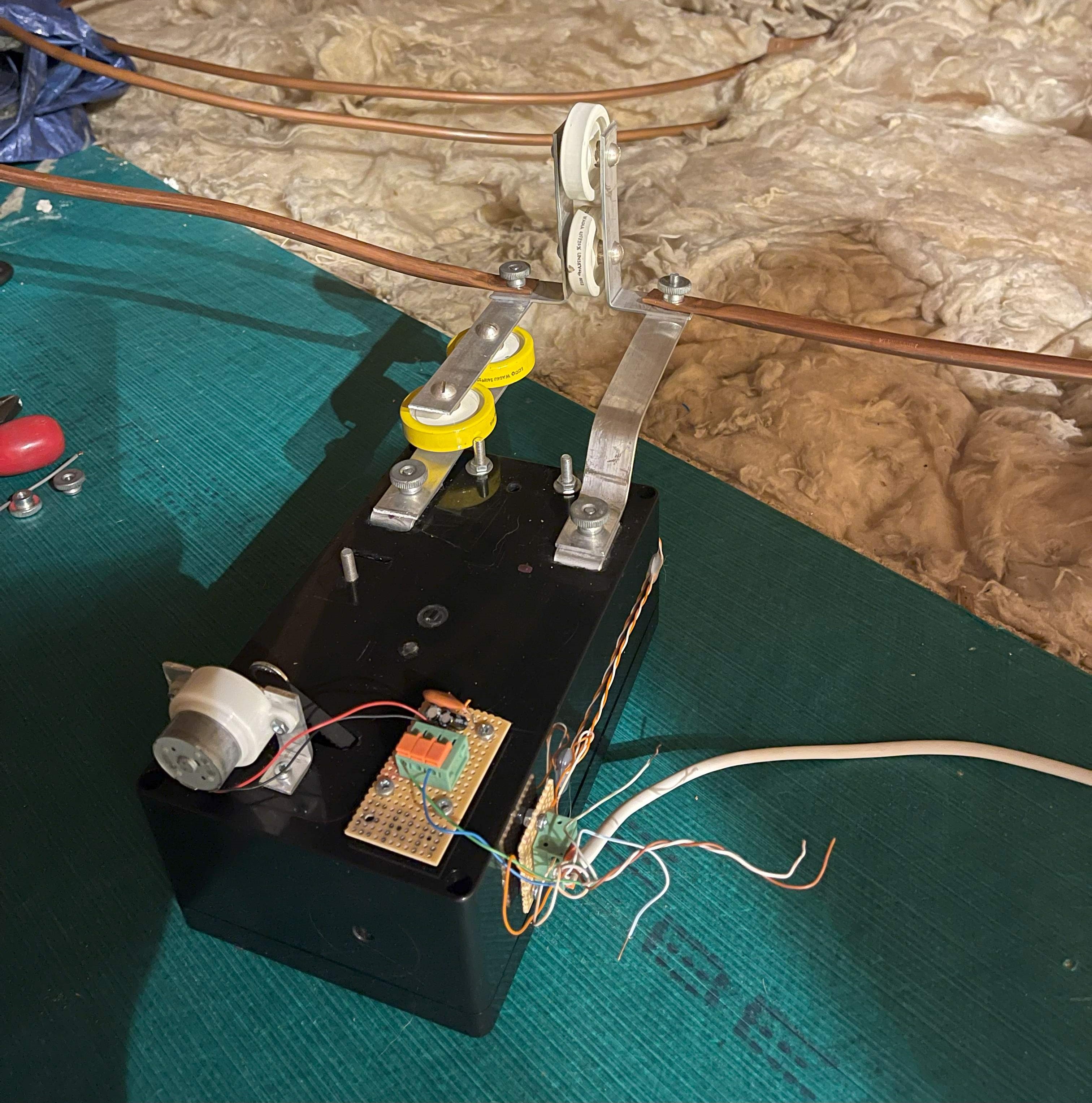
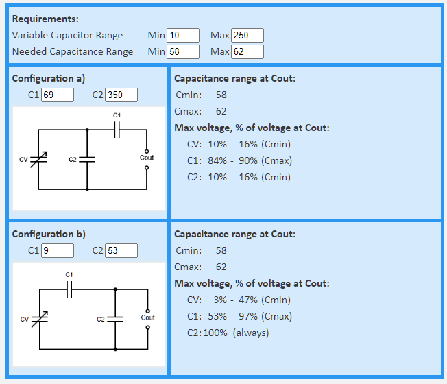
I did some experiments using doorknob capacitors to pad my air spaced variable (see main image above). It took a while for me to work out how to combine a 10-250pF variable with two 240pF doorknobs and two 47pF doorknobs to get operation on a suitable band to test versus the directly connected air spaced capacitor. This inspired me to create a calculator targetted at solving this kind of problem. Google searches reveal a few calculators for bandspread purposes on receivers, but nothing where you can enter a desired capacitance range and certainly nothing that will also conveniently show the reduction in voltage across the variable when used in a magloop. So, I created a calculator - link at the bottom of this page. The screenshot below shows a calculation for padding a 10-250pF variable for use on 40m with a large (7.5m circumference) magloop, showing a worthwhile reduction in the voltage across the variable capacitor.
Hopefully the calculator is useful to you!
Click the links below to get to the calculator and the mathematical explanation
