Maths for Calculating Padding Capacitors
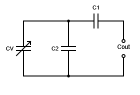
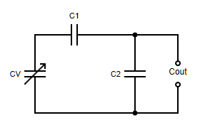
| Configuration a) | Configuration b) |
|---|---|
 |
 |
It’s easy to work out the range of capacitance achieved given the available range of the variable capacitor (e.g. 5pF to 250pf) and the values of the added capacitors, by using the well-known formulas for combining capacitors. However, it’s not so easy to work out what values you need for C1 and C2 in order to achieve a particular desired capacitance range. This requires a bit more as explained below.
Calculating the output capacitance
Click to expand
We can use the well-known formulas for capacitors in parallel \(C=C1+C2\) and series \(\frac{1}{C}=\frac{1}{C1}+\frac{1}{C2}\) to work out the output capacitance of each configuration for a particular value of its variable capacitor CV.
For Configuration a):
\[Cout=\frac{1}{\frac{1}{CV+C2}+\frac{1}{C1}}\]For Configuration b):
\[Cout=C2 + \frac{1}{\frac{1}{CV}+\frac{1}{C1}}\]Voltages across each capacitor
Click to expand
A capacitive divider is very similar to a resistive divider in that voltages divide according to the ratios of the impedances; higher voltages across higher impedances and vice versa. The maths looks different though because the reactance (equal to the impedance if the capacitor is perfect) is proportinal to the reciprocal of the capacitance.
So, for a simple capacitive divider comprising two capacitors C1 and C2 in series, the voltage across C1 is: \(V1 = Vin\frac{Ctotal}{C1}\) where \(Ctotal=\frac{1}{\frac{1}{C1}+\frac{1}{C2}}\) i.e. :
\[V1=\frac{Vin}{1+\frac{C1}{C2}}\]So, the voltages as a fraction of the voltage across Cout are:
| Capacitor | Configuration a) | Configuration b) |
|---|---|---|
| CV | \(\frac{1}{1+\frac{C2+CV}{C1}}\) | \(\frac{1}{1+\frac{CV}{C1}}\) |
| C1 | \(\frac{1}{1+\frac{C1}{C2+CV}}\) | \(\frac{1}{1+\frac{C1}{CV}}\) |
| C2 | same as V at CV | same as V at Cout |
Working out C1 and C2
Click to expand
Configuration a)
Let’s look first at the first configuration with the parallel capacitor connected directly across the variable one:
Let’s call the capacitance range we need A (min) to B (max) and the capacitance range of the variable capacitor similarly \(\alpha\) and \(\beta\).
From the capacitor combination formulas above we can see that
\[\frac{1}{A}=\frac{1}{C1}+\frac{1}{C2+\alpha}\]for the minimum capacitance, and
\[\frac{1}{B}=\frac{1}{C1}+\frac{1}{C2+\beta}\]for the maximum capacitance
Rearranging,
\[\frac{1}{C1}=\frac{1}{A}-\frac{1}{C2+\alpha}=\frac{1}{B}-\frac{1}{C2+\beta}\]If we multiply through with \((C2+\alpha)(C2+\beta)\), then expand those brackets and gather terms together, we find that the right hand equality (the one that doesn’t involve C1) shows C2 in a quadratic equation:
$$\displaylines{(\frac{1}{A}-\frac{1}{B})C2^2 \\\ +(\frac{\alpha}{A}-\frac{\alpha}{B}+\frac{\beta}{A}-\frac{\beta}{B})C2 \\\ +\frac{\alpha\beta}{A}-\frac{\alpha\beta}{B}+\alpha-\beta=0 }$$
Using the standard notation for quadratic coefficients a,b,c we have a quadratic with:
\[a=\frac{1}{A}-\frac{1}{B}\] \[b=a(\alpha+\beta)\] \[c=a\alpha\beta+\alpha-\beta\]… noting that, for convenience, the coefficient a appears in the expressions for coefficients b and c.
Then we can use the standard formula (using only the positive square root)
\[C2=\frac{-b+\sqrt{b^2-4ac}}{2a}\]To get C2, and then C1 follows easily from
\[\frac{1}{C1}=\frac{1}{B}+\frac{1}{C2+\beta}\]Configuration b)
For the other configuration, the maths is very similar and shows that this time C1 rather than C2 is quadratic with coefficients -
\[a=B-A+\alpha-\beta\] \[b=(B-A)(\alpha+\beta)\] \[c=\alpha\beta(B-A)\]This time we use the negative result of the square root to find C1:
\[C1=\frac{-b-\sqrt{b^2-4ac}}{2a}\]… and then get C2 from
\[C2=B-\frac{1}{(\frac{1}{C1}+\frac{1}{\beta})}\]