VHF AM Airband Superregen Receiver with Speaker and Squelch Circuit
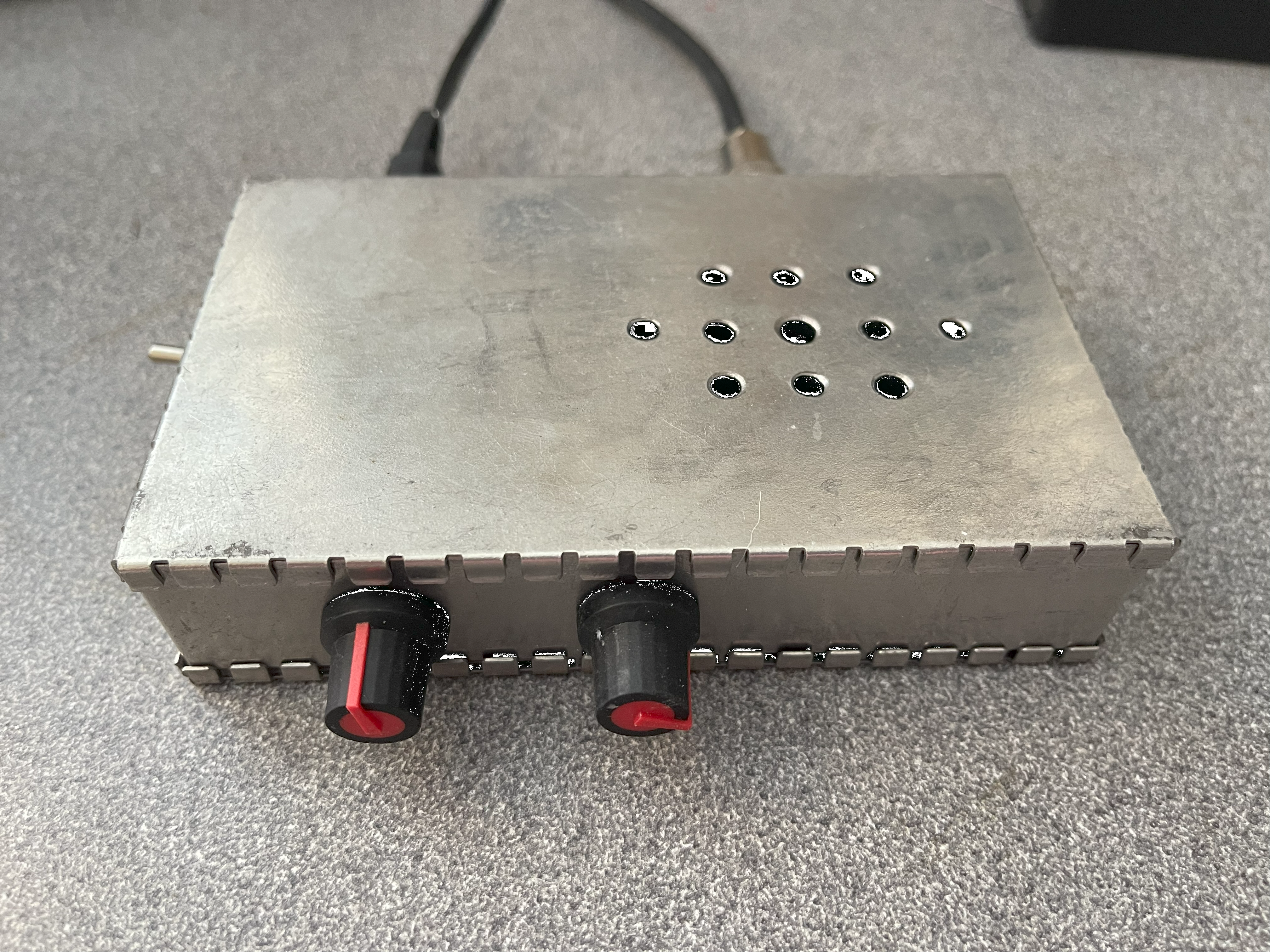
This page describes my Superregen VHF AM Airband receiver with Squelch, and provides some background around approaches to solving the problems of designing squelch circuits for superregen receivers.
This circuit has several advantages over a superhet design:
- Fewer components
- No alignment required
- Easy tuning
- AGC action inherent in the superregen circuit, so no AGC circuit needed
- Superregen “capture effect”
Circuit description
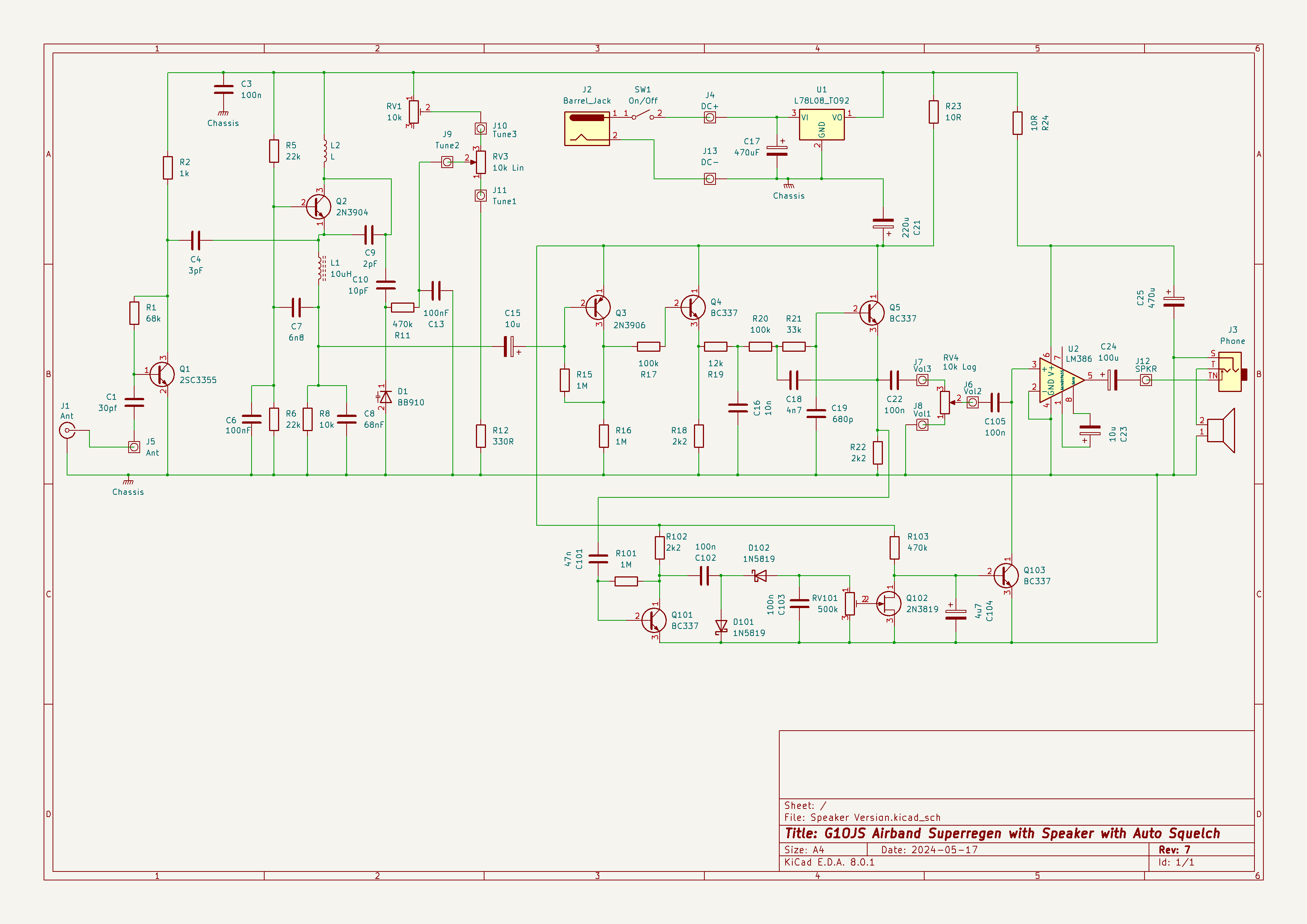
The diagram below shows the entire circuit diagram. The subsections below describe the operation of the various parts.
Superregen Receiver Oscillator Section
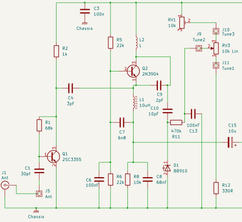
The Superregen circuit shown in the diagram below, based around Q2, is nothing new, and follows several designs available on the web. I have used an off-the-shelf ferrite inductor for the emitter lead choke (L1) rather than a home wound coil. L2 is then the only home-made component, and is about 5 turns of 0.9mm ECW air cored & wound on a former with a diameter of about 6mm.
As with all superregenerative oscillators (SROs), it is necessary to precede the circuit by an amplifier stage to avoid radiation of the oscillations produced by the SRO. Q1 performs this function and provides sufficient gain to allow the SRO to detect signals as low as -110 dBm.
Detector and Audio Chain
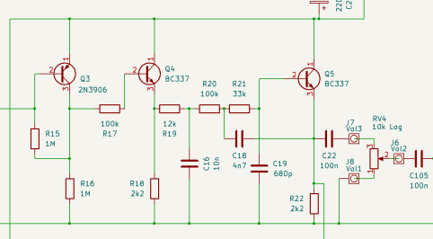
The diagram below shows the detector, buffer and audio filter.
The detector is Q3 & based on the configuration recommended in Dr Eddie Insam’s paper Designing Superregenerative Receivers. As Dr Insam states, this configuration does seem to improve the sensitivity of the SuperRegen Oscillator (SRO). After that the buffer Q4 feeds a single stage BJT Sallen Key Filter Q5 , and this provides enough signal level to present to the volume control and then on to the LM386 audio amp. The Sallen Key (SK) filter has a 3dB frequency of approx 1.5 kHz and a third order rolloff. The buffer is necessary to provide a low impedance drive to the filter circuit.
Note: I added the SK filter because I wanted to get the best possible audio from the receiver; I wanted to minimise hiss above highest modulation frequencies and design a “Rolls Royce” superregen audio chain. I have since found that the improvements to audio are slight (reasonably similar results can be had from my Earpiece Version) but the filter does, I think, provide a useful foundation for the minimal squelch circuit described below - I’m not sure it would work so well without the SK filter present in the audio chain.
Approaches to Squelch Circuits for Superregen Receivers
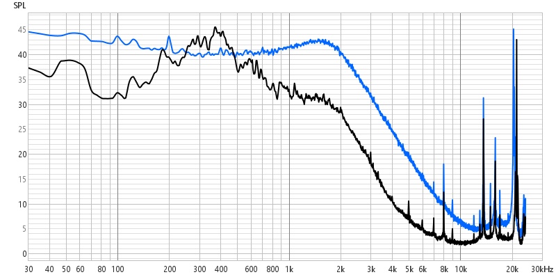
Squelch circuits can be quite tricky to implement in SRO receivers because the background noise under “no signal” conditions can be almost as loud as wanted signals when a carrier is present. The figure below shows the audio spectrum measured (averaged over 10s of seconds) at the emitter of Q5 - the output of the Sallen Key filter. The blue trace shows the receiver tuned to no signal, and the black trace shows the receiver tuned to a continuously broadcasting VOLMET station. It can be seen that, using the traditional audio squelch method of measuring the received level over the range containing demodulated audio (up to approx 2.5kHz in this design), it would be difficult to discriminate between no signal and wanted signal cases.
However, there are several ways around this problem, as described in the subsections below.
Note: the spectrum plot above also shows the strong signal at the quench frequency around 20kHz, even after the Sallen Key filter providing approx 67 dB rejection at this frequency. We can also see how the quench frequency is increased slightly when there is a carrier present.
Channel Quieting Squelch
The spectrum plot above shows that SRO noise falls by about 10dB in the kHz region when a carrier is present, and this change is easily detectable. The trick is to use a filter to exclude the modulated audio and the quench frequency component, so that we can monitor the level of the SRO noise only and detect this drop in level when a carrier is received. The demodulated audio must be excluded because that gets louder when the noise we are trying to use to open the squelch gets quieter.
A good example of this technique using a multiple-feedback narrowband bandpass filter based around an op-amp is described by Dayle Edwards on The RadioBoard here. Dayle’s implementation uses a narrow bandpass filter to “pick out” the SRO noise somewhere between the highest modulated audio frequency and the “quench frequency” (see spectrum plot above).
I tried this approach and found it to work, but found it difficult to implement with a low quench frequency - which I wanted for better selectivity - because the “gap” between the audio and the quench frequency was not wide enough to allow a filter to pick out the wanted SRO noise to monitor. I might come back to investigate this again.
Number of components required is about 16 plus one IC.
Traditional Audio Level Squelch
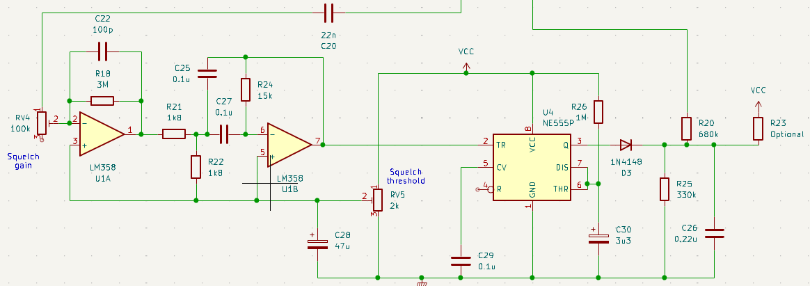
A traditional approach can be used if the demodulated audio is filtered tightly enough to remove the quench signal and as much of the “no signal” SRO noise as possible. This is in some ways the opposite of the Channel Queiting approach (looking for a strong wanted signal rather than quieted unwanted noise). I had some success with the circuit below, using two op-amps to do the tight filtering and gain, and an NE555 to act as the squelch trigger & hang time circuit. The NE555 is triggered directly off the audio signal. It is not necessary to use any kind of envelope detector here, as the NE555 has a precise trigger threshold and the monostable action ensures that even a brief excursion of the audio waveform across the trigger threshold is enough to open the squelch for the “hang time” set by C30 and R26. Any further excursions re-trigger the monostable and the squelch only closes one “hang time” after the very last such excursion.
Number of components required is about 19 plus two ICs.
Voice Cadence / Syllabic Squelch
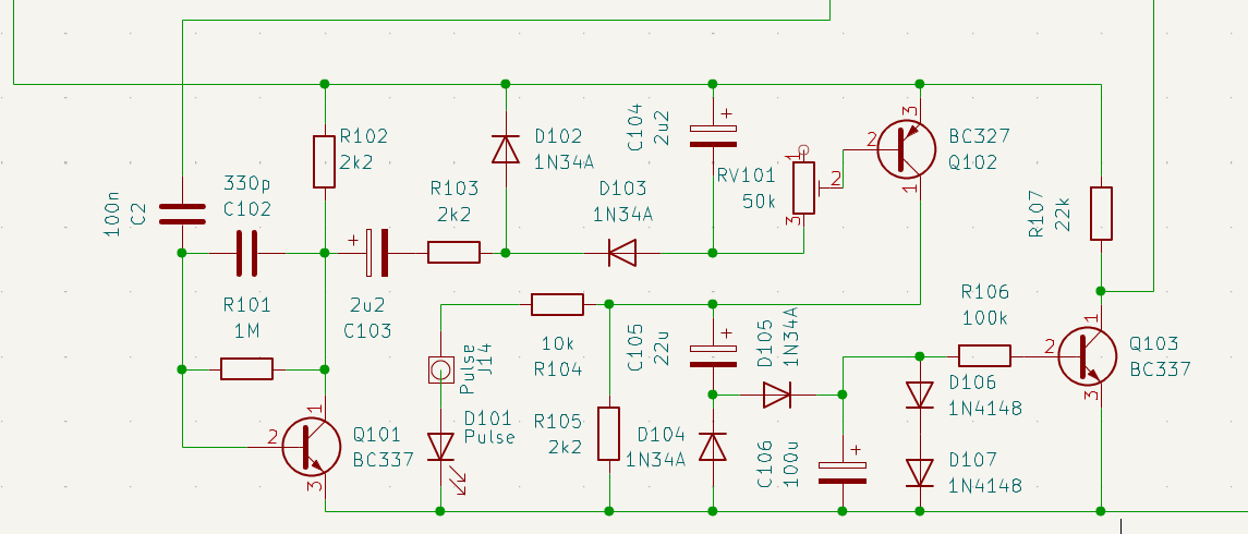
This circuit is an implementation of a type of channel activity squelch. The idea is to monitor the audio spectrum (again tightly filtered as in the approach immediately above) but instead of triggering the squelch based on the level of the audio, watch for changes in the audio level. This way, the squelch responds to the transition between “no signal” hiss and the quieted audio on reception of an unmodulated carrier, and also responds to the cadence of voice signals (the increase and decrease in volume across speech sounds is itself a signal that can be monitored).
The circuit operates as follows (& I haven’t yet seen it done like this!) :
- Q101 amplifies ~50mVpp audio at R22 to ~2Vpp. C103, R103, D102, D103, C104 form a Greinacher voltage doubler whose output follows the cadence of voice signals. Time constants are ~50mS (~20Hz).
- Q102 drives another Greinacher circuit whose output voltage represents the amplitude of the cadence signal (not the amplitude of the audio signal) - this amplitude is zero on constant carrier, constant noise or constant QRM equivalently as there is no variation in the cadence signal. Q102 is chosen to be PNP in order to provide a strong pull up on leading edges of the voice cadence signal.
- C106 & R106 set the squelch hang time (~1000mS) and drive Q103 to turn on whenever there is activity (as opposed to level) on the audio. The collector voltage of Q103 is used to control a pass component (such as a biased diode) between the volume control and output amplifier.
- D106 and D107 limit the charging of C106 to prevent the squelch hang depending on the amount/amplitude of activity prior to quiet.
An advantage of this circuit is that in addition to closing on “no signal” conditions, the squelch also closes on a) constant strong interference and b) constant carriers with no modulation.
Number of components required is about 22.
Squelch Circuit Used
The squelch circuit used monitors the “no signal” noise above the highest modulation frequency and watches for the amplitude of this to fall when a carrier is present (quieting). When this audio level falls below a threshold, the squelch opens. This is the “Chanel Quieting Squelch” approach in the “Squelch Circuit Background” section above, but is implemented with fewer components (and no op-amp ICs). This is achieved by omitting the tight bandpass filter and gain stage, and dealing with the implications of this as described below.

Although the sharp bandpass filter is omitted, this circuit takes advantage of the 3rd order low pass filtering provided by the Sallen-Key filter around Q5, and uses a fairly basic high pass filter (C101 working against the input impedance of Q101) to work with this and create a wider bandpass filter in aggregate.
A diode pump (Greinacher voltage doubler circuit) feeds a JFET (Q102) in a way that provides a fast rise time & fall time binary response at the drain of the JFET when audio levels drop below a threshold set by RV101. With very quiet audio (dead carrier or carrier with low level audio modulation) the diode pump produces an output close to zero volts; this leaves the JFET conducting and Q103 turned off, allowing audio to pass unhindered from the volume control to the LM386 amplifier. In the “no signal” condition, the SRO noise increases, and the diode pump produdes larger negative voltages which cause the JFET to turn off, biasing Q103 into conduction and shorting out the audio at the input to the LM386 amplifier.
The lack of a sharp bandpass filter means that strongly modulated carriers would cause the squelch to close on strong audio peaks unless other measures were taken in the squelch circuit design. This is dealt with as follows:
- Using fast time constants in the diode pump means that any potential unwanted squelch closed periods are not unnecessarily extended in time, and are confined to short periods on voice peaks only.
- A simple capacitor across the base-emitter junction of Q103 provides a “pulse stretching” or monostable function which maintains the “squelch open” condition across these short voice peaks, and also provides a short (but not too long) “hang time” for the overall squelch action. This capacitor doesn’t significantly affect the speed with which the squelch opens, because in this case it dischcarges rapildy through the low resistance of the conducting JFET rather than charging slowly through R103 as the squelch closes.
Note - with R103 at 470k, Q103 doesn’t fully saturate when the squelch is closed. This allows a small level of audio signal to pass the closed squelch, which can provide useful reassurance that the radio isn’t missing any wanted signals. If this is not desired, change this resistor to about 100k and, to keep the “hang time” unchanged, change C104 to 22u.
Number of components required is about 13.
Audio Amplifier Section
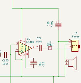
The audio amplifier uses a simple LM386 circuit, again aiming to keep the overall component count low.
Summary
This little receiver is very pleasant to use, and has a total component count of about 62 depending on what you count as a “component”!