Improved Accuracy
Spot Impedance Measurements - Resistive Loads
In terms of practical spot measurements, the tables below show some example loads with the absolute results and percentage error (for reactance, which should be zero for the resistive loads, I’ve expressed the percent error as a percentage of the true resistance).
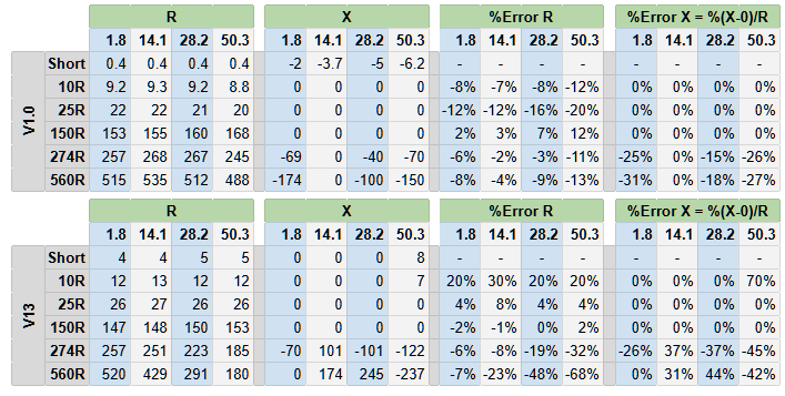
It is possible to control the variation of accuracy with impedance to some extent, by chosing the number and value of calibration loads. A future version of firmware may allow this as a user setting, so for example an experimenter focussing on low impedance Yagi designs might chose to concentrate calibration loads in the 10 to 40 ohms region.
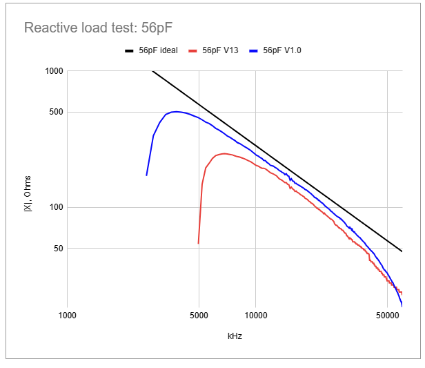
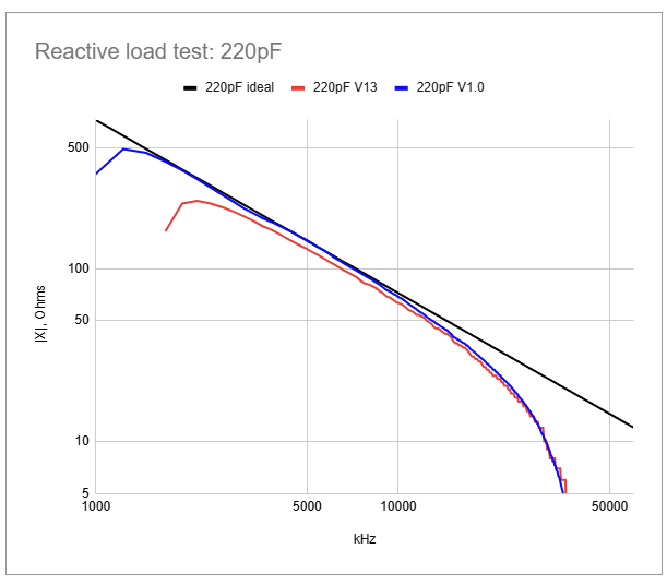
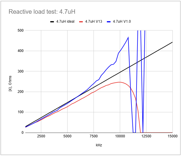
Frequency Sweeps - Reactive Loads
The graphs below show frequency sweeps with different capacitor and inductor values as loads. For the capacitor results, the V1.0 firmware has slightly better correspondance with the ideal value of reactance, and maintains this over a larger frequency range. For the inductive load, at lower frequencies again the V1.0 firmware is slighly more accurate, but at higher frequencies the V13 firmware seems to be giving a more true result (|X| falling as the inductor approaches a series resonance, tbc). The V1.0 firmware is certainly showing evidence of numerical calculation problems in this chart, probably because the dynamic range of the calibration storage encoding scheme has been set too low.
| 56pF Capacitor | 220pF Capacitor | 4.7uH Inductor |
|---|---|---|
 |
 |
 |